Developer documentation with PlantUML
At one of our last night schools, I presented a new way of documenting IT systems in a development-oriented way. The Night Schools are our internal training events, in which a colleague alternately prepares and presents a current topic from the software architecture area for the team.
The Unified Modelling Language UML is the current standard for the documentation of static structures and dynamic processes in IT systems. UML is also often used in architecture documentation.
However, UML does have its dark sides, as it is often created with complex modelling or drawing programs à la VISIO. The result of the modelling is then a series of Word or PDF files with embedded JPEG or PNG graphics. Developers, on the other hand, work with text files in a development environment that is often connected to a complex build pipeline and, if desired, can version and deploy all work results immediately. In this way, every change can be easily traced across all versions. Unfortunately, this approach fails with Office files, where each new version of a file is treated as an entirely new artifact. When modeling with UML, not only is there a media break, but the results of the work cannot be seamlessly integrated into the development pipeline. Plant-UML now jumps into this breach.
Die Idee von Plant-UML ist, mit Hilfe von einfachen Textdateien, 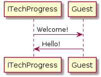
that use a specific Plant UML syntax, automatically generate UML diagrams and display them as PNG, SVG, or ASCII type. This is done interactively, so that the author can see the result of his work at the push of a button. On the Plant-UML Homepage you can easily try it out for free >> http://www.plantuml.com/plantuml/uml/. Supported are use case diagrams, class diagrams, sequence diagrams, activity diagrams, state machines, object diagrams, deployment diagrams, component diagrams and timing diagrams. All are defined using a simple syntax and automatically adopt the layout of the objects on the diagram. Nevertheless, a whole range of additional items can be used to make the UML diagrams even more meaningful. This ranges from configurable colors to legends and info boxes. What I like best is that Plant-UML can be integrated directly into the build process and that the UML diagrams can not only be inserted into ASCIIdoc documents, but that they are also generated anew with every build. This results in documentation that can be managed as easily and effectively as the source code itself. There is no media break.
Besides UML diagrams, Plant-UML can do even more: It is possible to describe database tables using entity relationship diagrams, to present new ideas in the form of mind maps and to describe work packages using work-breakdown diagrams (WBD). It is even possible to create project plans using Gantt diagrams as in MS Project. All these diagrams are defined just as easily with the help of text snippets. But the real highlight, in my opinion, is the possibility to create a wireframe of a surface from a text representation. Just give it a try and share your experience with us via the comments.
Axel Feix, Software Architekt & Managing Consultant bei ITech Progress